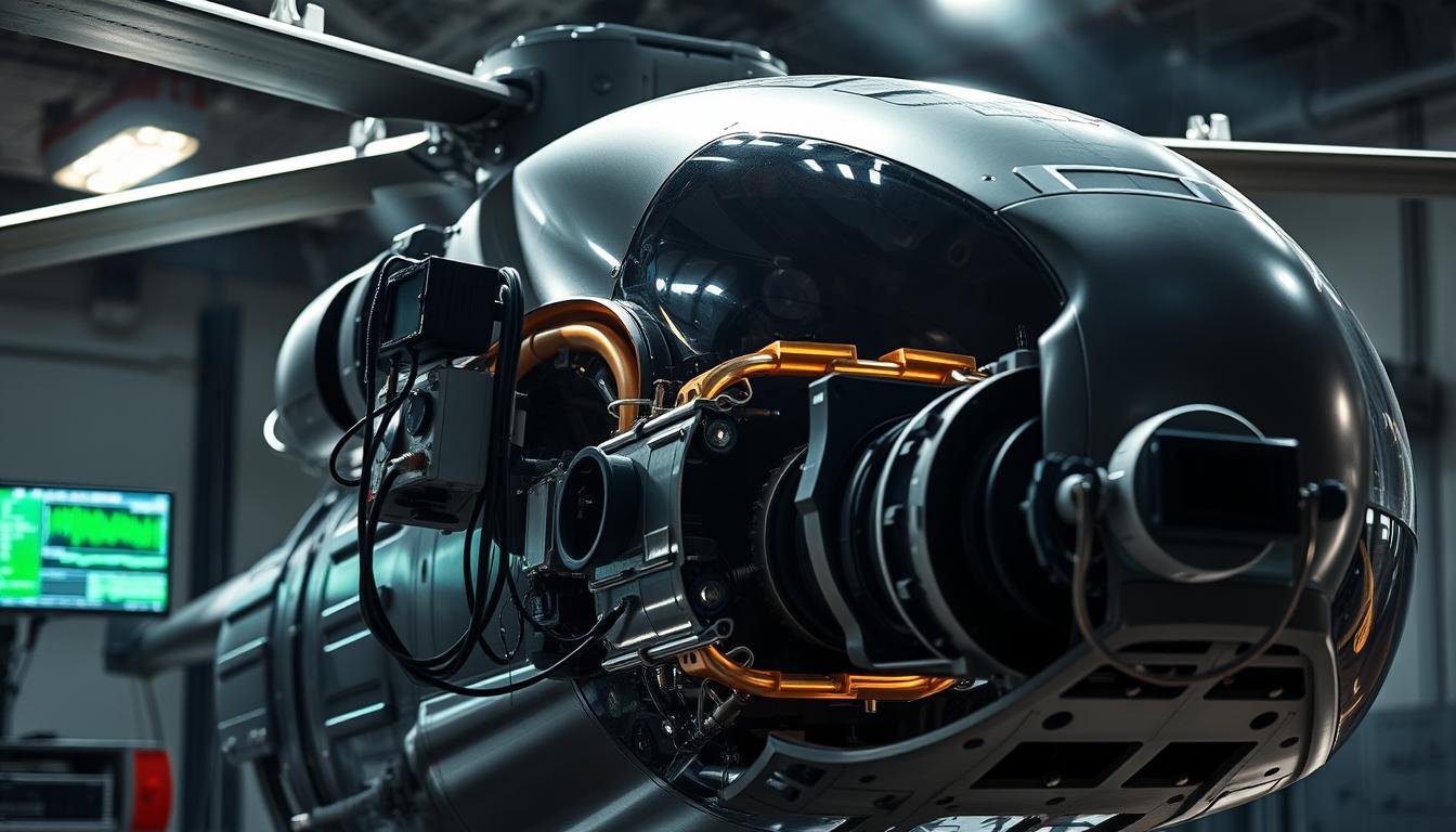
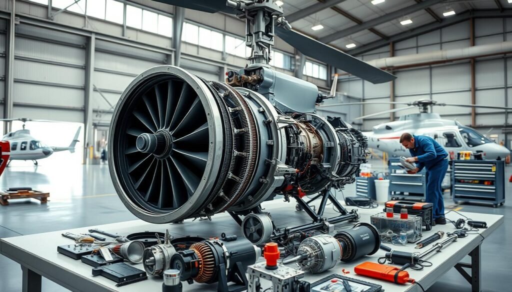
A single rotor signature can predict failure weeks before parts fail: helicopters commonly run at 0.05g–0.1g while jets sit below 0.01g, showing why targeted helicopter vibration analysis.
The team uses amplitude in IPS and phase against a rotor reference to spot faults early. This approach keeps rotor blades, gearboxes, and avionics from degrading unexpectedly. Modern spectral methods and remote sensors let crews watch trends in flight and on the ground.
Common culprits include loose hardware, worn bearings, and uneven mass on blades. Technicians prioritize repairs using clear thresholds — 0 IPS is “good,” and 1.2 IPS is considered dangerous — so work focuses where it will improve safety most.
For more technical background on signal processing and flight data checks, see the NASA study on archived flight monitoring and spectral methods in predictive maintenance via rotor condition monitoring. Practical field guidance and case examples appear in industry write-ups like the deep dive at understanding vibration prevention.
Key Takeaways
- Baseline Levels Matter: Helicopters have higher normal readings than jets; expect ~0.05g–0.1g.
- Use IPS and Phase: Measure amplitude and phase versus a rotor reference to pinpoint faults.
- Clear Thresholds Guide Action: 0 IPS is good; 1.2 IPS is dangerous and needs immediate attention.
- Common Causes Are Fixable: Loose parts, worn bearings, and unbalanced blades are frequent and detectable.
- Modern Tools Enable Prediction: Spectral sensors and remote monitoring shift teams from reactive to predictive maintenance.
Helicopter Vibration Analysis
Monitoring amplitude and phase relative to a rotor marker helps crews catch failing parts long before they break. This practice protects safety, extends component life, and preserves handling qualities for flight crews.
Why Monitoring Vibrations Matters For Aircraft Safety And Component Life
Early detection ties measured IPS and phase to specific rotor behaviors so sub‑danger levels do not silently increase fatigue in blades, bearings, or hubs. Teams treat the 1.01–1.2 IPS window and above as critical while still addressing lower readings that shorten service life.
Typical Vibration Levels And What They Mean In Flight
Low, medium, and high frequency types point to distinct faults: low often links to main rotor revolution issues; medium suggests loose hardware or rotor-system problems; high implicates gears, drive shafts, or accessory rotating elements.
Best practices:
- Classify by type and map frequency to rotor blade and tail harmonics.
- Anchor maintenance intervals to trend data to reduce unplanned downtime.
- Use recorded signatures to target blades, pitch links, hubs, or gearboxes precisely.
For a practical field approach and tools, consult the comprehensive helicopter vibration analysis guide.
How To Perform A Vibration Analysis On A Helicopter
A structured test plan sets the stage for reliable rotor diagnostics and repeatable results. The introduction below guides teams through tools, sensor layout, data capture, and advanced separation methods used in the field.
Plan The Inspection: Aircraft Configuration, Rotor Speed, And Environmental Conditions
Begin by documenting aircraft configuration, target rotor RPM ranges, and ambient conditions. Match runs to the expected flight envelope so measurements remain comparable across tests.
Select And Calibrate Tools: Dynamic Signal Analyzer, Accelerometers, And Velometers
Use a dynamic signal analyzer for synchronous capture. Mount calibrated accelerometers for high-fidelity readings and add velometers when instantaneous velocity data is needed.

Sensor Placement And Axes: Forward (X), Lateral (Y), And Vertical (Z)
Place triaxial sensors at consistent, repeatable locations. Define axes as X (forward), Y (lateral), and Z (vertical) to map signatures to physical directions and similar aircraft.
Collect Data: Amplitude (IPS) And Phase Relative To The Rotor Reference
Record amplitude in IPS at key power settings and capture phase against a rotor index. This pairing isolates unbalance, timing issues, and misalignment.
Balance And Track Rotors: From Unequal Mass To Blade Tracking Corrections
Address unequal mass with balance corrections and fix tracking with pitch or trim adjustments. Replace loose parts or worn bearings promptly to protect components.
Leverage Advanced Methods: Spectral Analysis, STAG Profiles, And Random/Sine Separation
Apply spectral order tracking to separate narrow rotational tones from broadband content. Generate sine-on-random profiles with STAG and evaluate residual random content with FDS. If a tach channel is missing, define a stable reference and keep parameters consistent.
For formal protocols and maintenance standards, consult federal maintenance guidance available here.
Interpret Results, Identify Root Causes, And Prevent Failures
Measured peaks and phase shifts provide the evidence teams need to find root causes fast. Technicians first classify the signature by frequency to narrow probable sources.
Classify By Frequency: Low-, Medium-, And High-Frequency Vibrations
Low frequency often traces to main rotor revolution issues. Medium frequency points to loose hardware in the rotor system. High frequency implicates gears, engines, fans, shafts, or tail‑rotor speeds.
Lateral Vs Vertical Issues: From Loose Components To Rotor Blade Misalignment
Pronounced lateral readings usually come from imbalance or cracked and worn parts. Vertical peaks commonly indicate rotor blade misalignment or tracking faults that require precise blade adjustments.

Detect Ground Resonance: Landing Gear, Tire Pressure, And Blade Dampeners
Ground resonance appears on the ground and can escalate quickly. Check landing gear setup, tire pressure, and blade dampener condition immediately to protect the aircraft.
Use Standards And Real Data: MIL‑STD‑810H Vs Aircraft‑Specific Test Profiles
MIL‑STD‑810H recommends using aircraft‑specific flight data when possible. Recorded profiles often show higher severity than standard envelopes, so teams extract sine orders with STAG and evaluate random content with FDS.
Case Insight: R22 Vs R44 Lateral Vibration And Fatigue Considerations
Comparative data show the R22 carries higher lateral energy (GRMS Y 1.457) and a ~200 Hz spike in the Y axis versus the R44. Use IPS and phase together to localize faults and prioritize maintenance actions that yield the largest safety gains.
For further guidance on identifying types and origins of these signatures, see this practical resource: identifying the types and origins of rotor.
Conclusion
Helicopter safety improves when teams tie IPS and phase checks to tailored testing and routine maintenance.
Evidence-based programs classify frequency content, link signatures to corrective action, and make balance and track work standard practice.
Converting recorded aircraft runs into sine‑on‑random profiles aligns tests with real rotor dynamics and reduces the risk of under‑testing components.
Teams should review lateral and vertical signatures regularly and verify ground resonance drivers so small faults do not grow into damage.
For deeper technical context, consult the definitive DTIC review at rotor safety research and the archived rotor research for modeling and test guidance.
FAQ
What is the main purpose of monitoring rotorboard motion and structural response?
Monitoring rotorboard motion and structural response helps prevent component failures and extends aircraft service life. Technicians track motion of the rotor system and airframe to detect early signs of imbalance, mis-tracking, or wear on blades, dampers, and flight controls. Early detection reduces unscheduled maintenance and enhances flight safety during both cruise and hover.
How are measurements taken during a diagnostic session?
Technicians use calibrated accelerometers, velometers, and a dynamic signal analyzer to capture amplitude and phase data relative to the rotor reference. Sensors mount on forward (X), lateral (Y), and vertical (Z) axes at critical points such as the mast, blade roots, and airframe hardpoints. Data collection includes IPS readings, frequency spectra, and engine/rotor speed logs under specific flight or ground run conditions.
What are typical acceptable levels for blade and airframe motion?
Acceptable levels vary by make and model, but common practice compares measured amplitudes against manufacturer limits and MIL-STD guidance. Low-frequency lateral or vertical excursions under specific RPM ranges often signal tolerable conditions if within prescribed thresholds. If readings exceed limits, corrective work such as track, balance, or component replacement is required.
How does balance differ from tracking when correcting a vibration issue?
Balancing corrects unequal mass or inertia distribution across the rotor head, while tracking aligns blade tip paths so all blades follow the same plane. Balance adjustments typically add or remove weight at pitch links or blade roots. Tracking uses pitch changes or trim to align blade tip traces. Both actions often combine to reduce residual motion across axes.
What causes ground resonance and how is it mitigated?
Ground resonance occurs when landing gear or damping systems couple with rotor dynamics, producing self-excited oscillations at low frequencies. Contributing factors include worn dampers, incorrect tire pressure, or loose components. Mitigation involves immediate engine throttle control, correcting damper condition, adjusting tire pressure, and addressing undercarriage wear or structural looseness.
When should advanced spectral techniques be used?
Spectral analysis, STAG profiling, and random/sine separation become necessary when basic time-domain checks fail to pinpoint root causes. These methods separate harmonics, identify sidebands, and isolate synchronous versus non-synchronous energy. They are essential for diagnosing gearbox, driveline, and complex aerodynamic coupling problems.
How often should routine inspections include motion monitoring?
Routine inspections should include motion checks at intervals defined by the manufacturer and based on aircraft utilization. High-usage aircraft require more frequent checks—especially after events like hard landings, component replacement, or control-system work. Incorporating spot checks into daily preflight and scheduled maintenance cycles improves reliability.
What role do standards such as MIL-STD-810H play in diagnostics?
Standards like MIL-STD-810H provide test profiles and environmental criteria that help validate sensor setups and baseline responses under controlled conditions. Technicians use these standards alongside aircraft-specific limits to ensure measurement repeatability and to compare field data with documented tolerances.
Can blade fatigue be detected through regular monitoring, and how?
Yes. Repeated monitoring of spectral content and amplitude growth over time reveals trends consistent with fatigue. Increases in harmonic content, changes in phase behavior, or progressive amplitude rises at specific frequencies often precede visible damage. Trend analysis prompts targeted inspections of blade roots, spars, and attachment components.
Are there differences in diagnosing small two-seat models versus larger turbine types?
Diagnosis principles remain the same, but thresholds, sensor placement details, and common failure modes differ. Light piston machines often show pronounced lateral issues tied to rotor track, whereas larger turbine types may reveal drivetrain or engine-induced harmonics. Technicians adapt toolsets and correction methods to the aircraft type and its service history.
Related Articles
- Understanding Helicopter Vibration Analysis: Key to Preventing Major Failures
- How AI and Big Data Are Shaping the Future of Helicopter Maintenance
- Upgrading Helicopter Systems: When and Why to Modernize Your Aircraft
- The Importance of Regular Avionics Checks for Helicopter Performance
- Helicopter Maintenance in Extreme Weather Conditions: What Technicians Need to Know
More from This Category
- Digital Cockpits: How Modern Technology Is Transforming Helicopter Navigation
- The Role of Predictive Maintenance in Helicopter Fleet Management
- Innovative Materials in Helicopter Design: Enhancing Durability and Efficiency
- How Helicopter Technology Is Revolutionizing Emergency Response Operations
- Rotor Blade Maintenance: Why It’s Critical for Safe Flight
- The Future of Autonomous Helicopters: What Technology Holds for the Aviation Industry
- Helicopter Engine Maintenance: Best Practices for Longevity and Efficiency
- How Advances in Avionics Are Improving Helicopter Safety and Performance
- Routine Helicopter Maintenance Checklist: What Every Pilot Should Know
- The Evolution of Helicopter Technology: From Early Models to Modern Innovations


